Skip to content
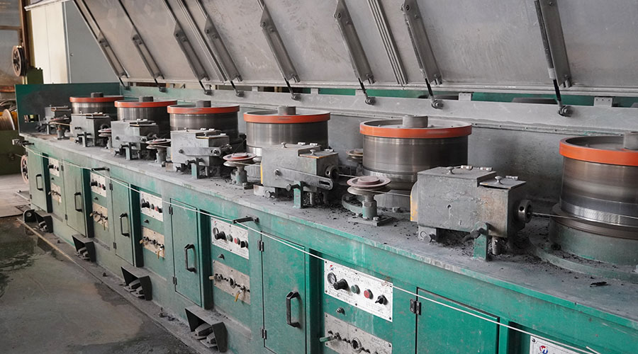
According to different process requirements, the drive motors of the I-beam take-up machine include ordinary AC motors, AC torque motors, electromagnetic speed-regulating motors, variable frequency motors, and DC motors. The choice of motor type determines the performance of the take-up machine to a large extent and is also related to its cost.
For systems that do not require strict take-up tension, torque motors, and electromagnetic speed-regulating motors can be selected; high-speed take-up machines equipped with loopers or take-up machines requiring tension can use variable frequency or DC-controlled motors.
There are 2 ways to I-beam take-up machine:
(1) When the take-up wheel drives the unwinding frame to rotate synchronously, add a take-up mechanism;
(2) When the take-up wheel and the unwinding frame rotate independently, the unwinding frame can achieve the function of taking up the line while rotating.
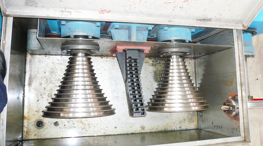
Generally, the first type is simple in structure, economical, and practical. The inverted take-up mechanism includes a frame. A reduction motor is arranged above the frame. The output shaft of the reduction motor drives a hollow shaft. A drum is fixedly sleeved on the hollow shaft, and a pulley set is provided on one side of the drum. , a deformer is provided on one side of the pulley block, and a roller is provided on one side of the deformer.
Characteristics of the first structure I-beam take-up machine
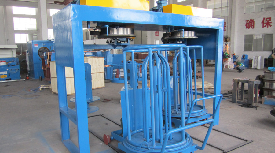
- There is a trolley under the frame. The trolley panel is at an angle of 5 to 8 degrees with the horizontal plane. There is a second reduction motor on the underside of the trolley panel. The output shaft of the second reduction motor is connected to the pinion;
- There is a main shaft in the middle of the trolley and a large gear on the upper end of the main shaft. The large gear meshes with the small gear;
- Set the bottom plate of the take-up frame on the large gear, and the claw-shaped take-up frame on the bottom plate of the take-up frame.
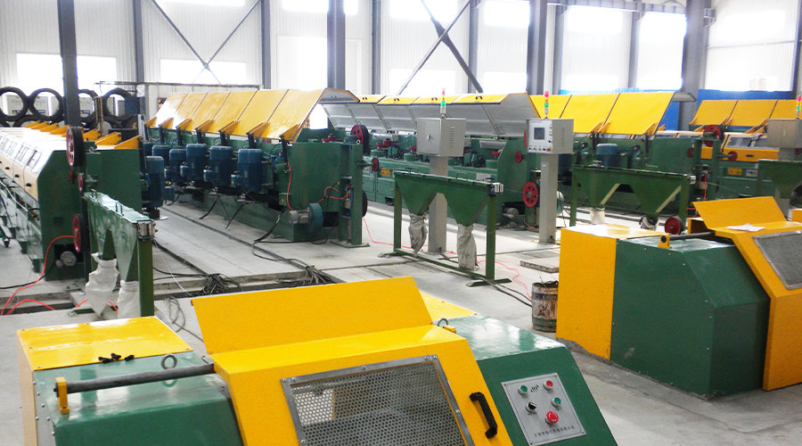
The advantages of the first structure I-wheel take-up machine are: it is suitable for the production of large steel wire reconnections, the equipment is easy to operate, has low labor intensity, runs smoothly, has a wide adjustment range, and is not easy to mess up the wire.
I-shaped wheel take-up machine process requirements
- Reset the cable arrangement, press the start button, and turn the speed control button to make the motor run at low speed, move the cable arrangement to a certain end, (if it is a polished rod, you can directly arrange the cable arrangement to one end of the I-shaped wheel) and stop the car.
- Install the I-beam take-up machine: Pull up the locking pin on the right runner, rotate it 90 degrees to open the lock, turn the wheel to push the right side of the empty I-shaped wheel, turn the handle to push into the I-shaped wheel, and lower the I-shaped wheel. The wheel bracket rotates the I-wheel at the same time to tighten it, and the locking pin rotates 90 degrees and enters the groove to lock.
- Wire threading: Guide the steel wire to the I-wheel through the guide wheel system, bend the steel wire head insert it into the locking hole of the I-wheel, and use the manual I-wheel to wind the steel wire 2-3 times.
- Close the door: Close the protective cover and plug in the latch
- Take up the line: rotate the speed evenly so that the speed of the I-wheel starts from slow to fast and starts to take up the line.
- Unload the I-wheel: After the I-beam take-up machine is fully wound, press the parking button: Turn the air valve handle, lift the I-wheel bracket, slide the table to the left, pull up the right locking block, and rotate it 90 degrees, open the locking device, turn the handle, release the right hand, remove the I-wheel and transport it away, and then enter the next cycle over and over again.