Skip to content
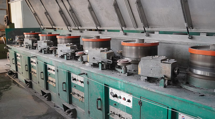
The maximum reduction per pass in wire drawing refers to the maximum amount of material that can be removed from the original cross-sectional size of the wire during a single pass through the wire drawing machine. This parameter is important because it determines the efficiency and productivity of the wire drawing process, as well as the resulting finished part dimensions and dimensional accuracy.
The maximum reduction per pass in wire drawing depends on several factors, including the type of wire used, the gauge of the wire, the diameter of the wire, the hardness of the wire, the shape and size of the wire feeder, the number of rollers in the wire drawing machine, and the speed of the wire feed. In general, higher-quality wire with a lower hardness will require more passes to achieve the desired reduction in cross-sectional size, while lower-quality wire with a higher hardness will require fewer passes.
To calculate the maximum reduction per pass in wire drawing, several formulas can be used, depending on the specific requirements of the application. One common formula is:
Maximum reduction per pass = (diameter of finished part) / (original diameter of wire) * (number of passes required)
For example, if a finished part diameter of 1 inch is required and the original diameter of the wire is 0.5 inch, then the maximum reduction per pass would be:
Maximum reduction per pass = 1 / 0.5 * (number of passes required) = 2 * (number of passes required)
This means that for every 2 passes through the wire drawing machine, one inch of material can be removed from the original cross-sectional size of the wire. However, this calculation does not take into account any other factors that may affect the efficiency and productivity of the wire drawing process, such as changes in wire hardness or wear on the rollers.
To determine the actual maximum reduction per pass in wire drawing for a given application, it is necessary to perform experiments using different types and sizes of wire, as well as adjust the settings of the wire drawing machine based on real-world conditions. By carefully monitoring and analyzing the results of these experiments, it is possible to optimize the wire drawing process and achieve maximum efficiency and productivity while maintaining consistent dimensional accuracy and part quality.
In addition to selecting the right type and size of wire for the application, there are several other factors that can affect the maximum reduction per pass in wire drawing. These include:
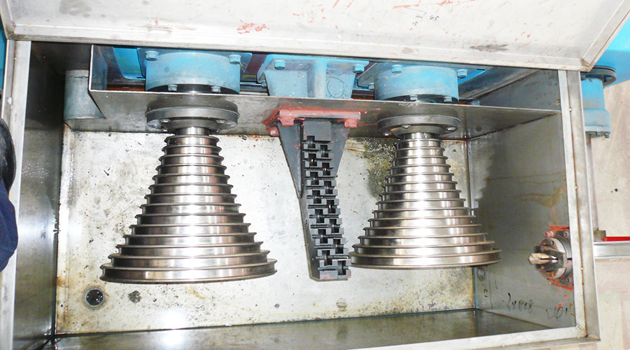
- Roller design: The design and construction of the rollers used in the wire drawing machine can have a significant impact on its performance. High-quality rollers made from durable materials such as tungsten carbide or ceramic can provide smoother and more precise movement along the length of the wire, which can result in better reduction per pass.
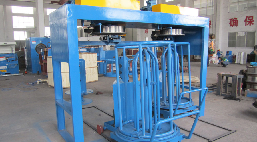
- Feeder design: The design and construction of the feeder mechanism used in the wire drawing machine can also affect its performance. A well-designed feeder with adjustable tension and speed control features can help ensure consistent feeding rates and prevent uneven wear on the wire.
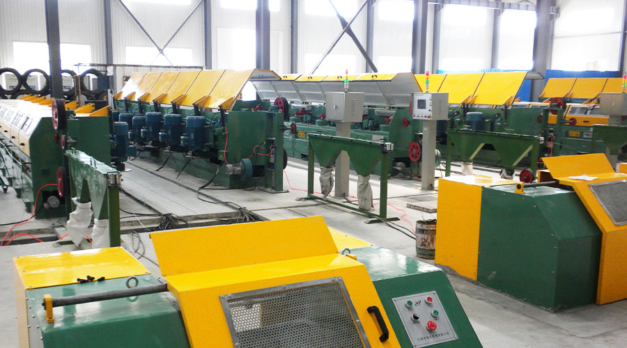
- Maintenance: Proper maintenance of the wire drawing machine is essential for achieving optimal performance over time. Regular cleaning and lubrication of moving parts such as rollers and bearings can help extend their lifespan and improve their precision and accuracy.
- Training: Finally, proper training and operator familiarity with the wire drawing machine is critical for achieving consistent results and minimizing downtime due to machine failure or operator error. By providing comprehensive training and ongoing support, manufacturers can ensure that their operators are able to use the wire drawing machine effectively and efficiently, maximizing its potential for high-quality production output.