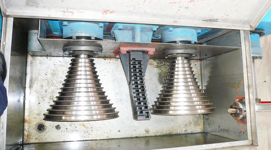
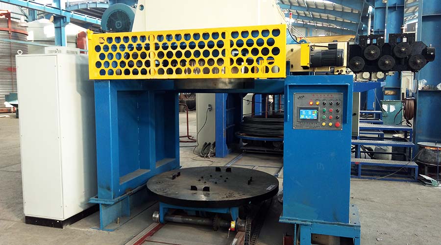
The use of variable frequency speed regulation in the control of straight wire drawing machine has the characteristics of simple configuration, clear logic, and reduced costs. At the same time, this article also introduces in detail the application of frequency converters on wire drawing machines.
1. Introduction of Straight Wire Drawing Machine
Metal products are an important part of the metallurgical industry, but this industry is a weak link in our country.
Outdated mechanical and electrical equipment hinders the development of the industry. In metal processing, the straight-forward wire drawing machine is a common one.
In the past, it was usually realized by a DC generator-motor unit (F-D system).
Now with the advancement of process technology and the widespread popularity of frequency converters, frequency conversion control.
It began to be widely used in straight wire drawing machine and can realize drawing variety settings, operation automation, production process control, real-time closed-loop control, automatic meter counting, and other functions through PLC.
It adopts the straight-forward wire drawing machine technology of a frequency conversion speed regulation system, which saves significant energy. The speed regulation range is 30:1 during normal operation, and it can provide more than 1.5 times the rated torque at 5% of the rated speed.
This article takes the frequency conversion transformation of a linear wire drawing machine that produces stainless steel wire in a factory as an example to illustrate the application process and effect of frequency conversion control.
2 Straight-forward wire drawing machine frequency conversion control system
This straight-in wire drawing machine mainly draws the finished stainless steel wire.
The design process requirements are
(1) Wire drawing speed 600m/min;
(2) There are three main types of processing, namely, incoming wire 2.8mm → outgoing wire 1.2mm, 2.5mm→1.0mm, 2.0mm→0.8mm;
(3) No more than 2 heads will be broken during an emergency stop.
The straight wire drawing machine is one of the most difficult-to-control wire drawing machines. Because it uses multiple motors to stretch the metal wire at the same time, the operation efficiency is very high. Unlike the water tank wire drawing machines and looper wire drawing machines often encountered before, the metal wire is allowed to slip between the various molds.
At the same time, it has high requirements for the synchronization of the motor and the rapidity of dynamic response. Because stainless steel is relatively brittle and lacks the toughness of high-carbon steel wires or steel cords, it is easier to break during operation.
There are eight 11KW frequency converters in this system. The electrical configuration of the system is a looper, installed on the stage. Its function is to pull the rolled stainless steel wire to the drawing part.
Since the looper can slide freely, this motor does not require special control. There are six drums with a diameter of 400mm in the drawing part. A cylinder swing arm is installed between each drum to detect the position.
A displacement sensor can be used to detect the position of the swing arm. When the wire is pulled tight, the wire will generate pressure on the cylinder of the swing arm, causing the swing arm to move downward.
The last part is the winding motor. This part uses a self-sliding tapered bracket. The winding diameter does not change during the whole process, so there is no need to use the winding diameter calculation function. The power of eight motors adopts special frequency conversion motors and are equipped with mechanical braking devices.
The system logic control of the straight wire drawing machine is relatively complex, with various linkage relationships, and is implemented by PLC. Synchronization control is all implemented inside the Inovance MD320 inverter and does not rely on external control.
Straight-in wire drawing machine’s working principle is: that the operator determines the speed of the operation based on the panel settings, and the analog signal of this speed enters the PLC. The PLC outputs the analog signal according to a certain slope after considering the acceleration and deceleration time. The purpose of this is mainly to meet the needs of some operations such as inching and threading.
The analog voltage signal output by the PLC is simultaneously connected to the AI2 (AI1 can also be used) input terminals of all frequency converters as the main speed-given signal. The signal of each swing arm displacement sensor is connected to the corresponding drum drive inverter as a feedback signal for PID control.
According to the position of the swing arm in the middle, set a given value of PID yourself. This system is a very typical PID control system with feedforward, one level in series, and one level in series, with PID as the fine-tuning amount.
The reason why the frequency converter was chosen is that it can easily realize the main speed following and PID fine-tuning functions without the need for an additional control board.
The parameter settings in this Straight wire drawing machine system are as follows:
F0-03=2: The main frequency source X is AI2
F0-04=8: Auxiliary frequency source Y is PID
F0-07=1: The frequency source is selected as main frequency source X + auxiliary frequency source Y
FA-00=0: PID given source is given by numeric keyboard
FA-01=4: PID setting value (the base value of this value is the feedback amount of the system)
FA-02=0: PID feedback value AI1
FA-03=0: PID action direction (when the feedback signal is greater than the PID reference, the inverter frequency output is required to decrease to achieve PID balance)
FA-05=25: P value of PID
FA-06=1: I value of PID
FA-07=0.08: D value of PID
FA-08=0.1: Sampling period of PID?
FA-09=0: PID deviation limit
Since the stability of the system depends to a large extent on the PID function, the tuning of its parameters must be carefully considered, including low speed, high speed, speed up speed down, etc. In addition, differential limiting must be added to this system.
3 Conclusion
After optimizing the parameter values of this straight wire drawing machine system, the speed of the equipment was very stable at 600 meters/min during the test run, which completely solved the problem of instability at high speeds when the synchronization plate was used (originally it could only operate up to 300 meters/min). Through comparative tests under various working conditions, the performance is the same as that of the wire drawing machine using imported DC drives.
At the same time, the equipment efficiency is 90-95% and the power saving rate is about 40%. Moreover, the electrical components of this system are configured concisely, the logic is clear, and the cost is greatly reduced compared with the original. It is indeed cost-effective.


