Skip to content
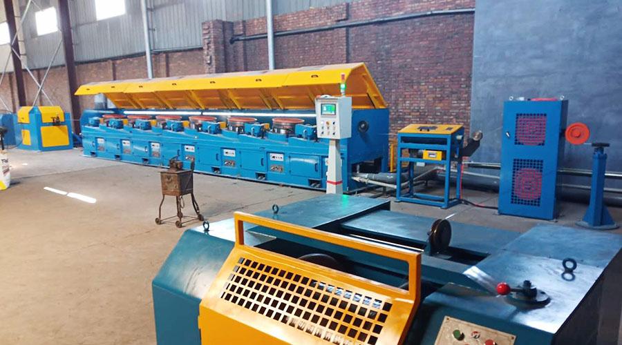
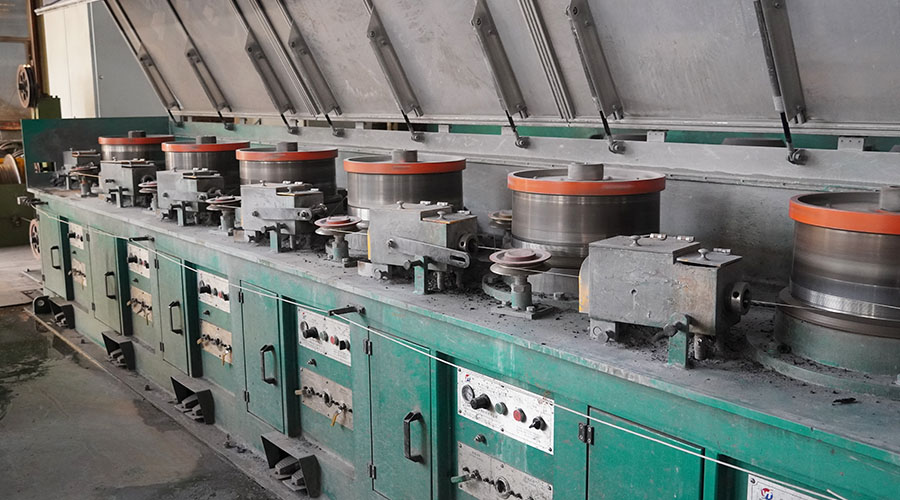
In metal processing, the straight-forward wire drawing machine is a common one. In the past, it was usually realized by a DC generator-motor unit. Now with the advancement of process technology and the widespread popularity of frequency converters, frequency conversion control has begun to be used in direct current.
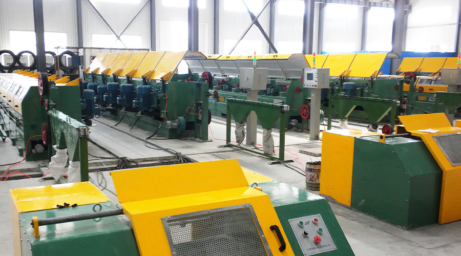
It is widely used in feed wire drawing machines and can realize drawing variety settings, operation automation, production process control, real-time closed-loop control, automatic meter counting, and other functions through PLC.
It adopts the straight-forward wire drawing machine technology of a frequency conversion speed regulation system, which saves significant energy. The speed regulation range is 30:1 during normal operation, and it can provide more than 1.5 times the rated torque at 5% of the rated speed.
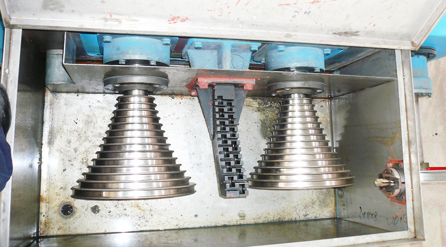
The straight-forward wire drawing machine mainly draws the finished stainless steel wire, but it is also one of the wire drawing machines that is difficult to control. Since it uses multiple motors to draw the metal wire at the same time, the operation efficiency is very high.
The straight-forward wire drawing machine allows the metal wire to slip between the various molds. At the same time, it has high requirements for the synchronization of the motor and the rapidity of dynamic response. Because stainless steel is relatively brittle and lacks the toughness of high-carbon steel wires or steel cords, it is easier to break during operation.
The system logic control of the straight-forward wire drawing machine is relatively complex, with various linkage relationships, and is implemented by PLC.
Synchronization control is all implemented inside the Inovance MD320 inverter and does not rely on external control. The speed of the operation is determined by the operator’s settings on the panel.
The analog signal of this speed enters the PLC. The PLC outputs the analog signal at a certain slope after considering the acceleration and deceleration time.
The purpose of this is mainly to meet the needs of some operations such as inching and threading. The analog voltage signal output by the PLC is simultaneously connected to the AI2 input terminals of all frequency converters and serves as the main speed-given signal.
The signal of each swing arm displacement sensor is connected to the corresponding drum drive inverter as a feedback signal for PID control. According to the position of the swing arm in the middle, set a given value of PID yourself.
This system is a very typical PID control system with feedforward, one level in series, and one level in series, with PID as the fine-tuning amount.