Rotary Motion and Reciprocating Motion of Wire Drawing Machine and Air Duct Design
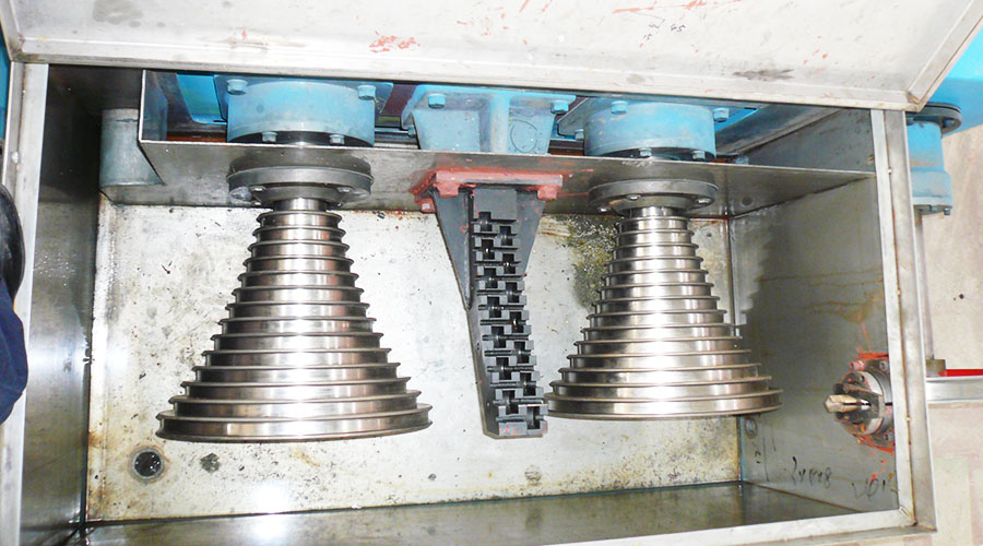
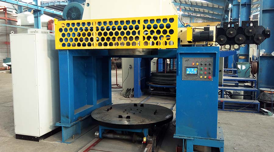
During the operation of the wire drawing machine, its structure adopts an independent air duct design. The fan can be freely disassembled during operation, and the entire equipment has good heat dissipation.
When in use, you can choose between vector control without PG, vector control with PG, torque control, and V/F control. It has powerful input and output multi-function programmable terminals, speed-regulating pulse input, and two analog outputs.
The wire drawing machine has a wide voltage input, automatic output voltage stabilization (AVR), and does not stop the machine after instantaneous power failure.
It has stronger adaptability. The built-in PID algorithm has fast response, strong adaptability, simple debugging, 16-segment speed control, and simple PLC to realize timing, Multi-function logic control such as fixed speed and orientation, and multiple flexible control methods to meet the requirements of various complex working conditions.
Safety Operating Procedures for Wire Drawing Machines
- Operators must hold a wire drawing machine operating qualification certificate, and unlicensed personnel are strictly prohibited from operating the machine.
- Operators must perform productive processing operations on designated equipment. Non-machine personnel are strictly prohibited from operating on the machine or operating in tandem.
- Operators must be familiar with the basic technical parameters and performance indicators of this equipment.
- Operators must be loyal to their duties, conscientious and responsible, and proficient in the operation, maintenance, and upkeep of this equipment.
- Operators must constantly summarize and learn to continuously improve their quality.
The movement of the spiral steel wire arranging shaft of the wire drawing machine is divided into rotational motion and reciprocating motion: the rotational movement is realized by the arranging motor through the synchronous belt transmission, and the reciprocating motion is realized by the servo motor through the synchronous belt, rolling screw assembly, and linear bearing transmission.
The reciprocating stroke is between 50 and 200mm. The reciprocating stroke can be adjusted by changing the positions of the two limit sensors.


