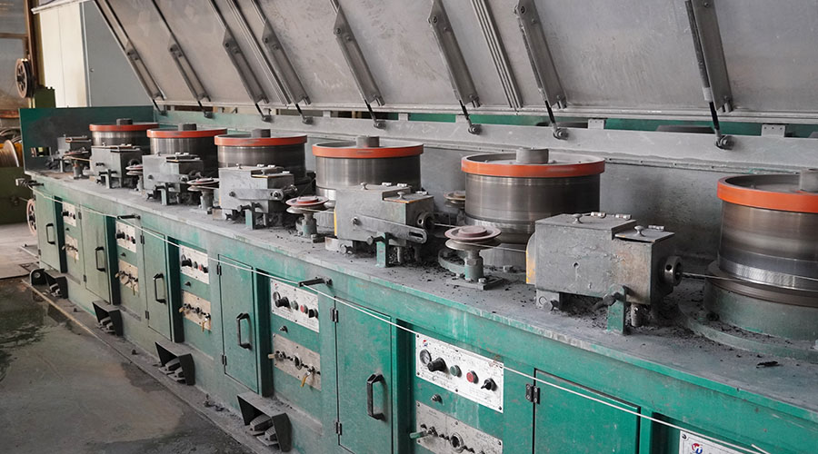
The high speed copper wire drawing machine is mainly used for drawing copper wire, and its main electrical transmission part is composed of a drawing motor, a wire take-up motor, and a wire arranging motor.
Other auxiliary parts of the equipment are composed of the pendulum (tension frame), positioning wheel, line dividing wheel, reciprocating line rod, and so on.
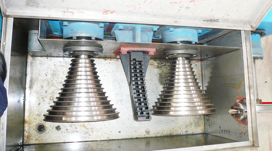
The drawing motor drives the wire drawing wheel to run, the four-stage wire drawing wheel is linked by the belt to realize metal stretching, and the wire take-up motor realizes winding. The equipment overview and functional requirements are as follows:
1.1 Basic parameters of high-speed copper wire drawing machine equipment:
Product name: High-speed fine wire stretching copper wire drawing machine
Drawing motor (KW): 11/4P
Take-up motor (KW): 4/4P
Incoming wire diameter (mm): Φ0.6-1.20
Outlet wire diameter (mm): Φ0.08-0.32
Maximum mechanical speed (m/s): 2500(max)
The resistance value of the tension frame: 5KΩ 1.
2 Technical specifications and requirements:
◎ Synchronization requirements when the equipment starts to speed up;
◎ Keep the tension constant when the equipment is running;
◎ Synchronization is required when parking and there is no broken wire or tension relaxation;
◎ Disconnection protection required by equipment safety production;
◎ Jog threading function;
◎ External button to start and run;
◎ Running speed display;
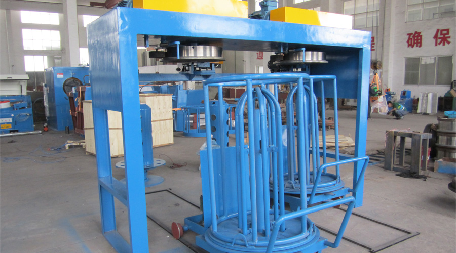
◎ The diameter ratio of empty reel to full reel is about 1:3;
◎ The weight of the full plate is about 50kg;
◎ The maximum operating frequency is about 70HZ.
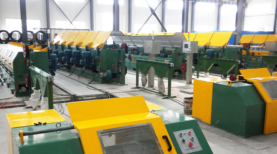
High-speed copper wire drawing machine system composition
◎ Select the following models and components as electrical transmission equipment according to the equipment conditions
INV1: Drafting Inverter S011Z3
INV2: Winding Inverter S004G3
Brake resistor: 1000W/70Ω
◎ The drawing motor adopts S011Z3 frequency converter, and the winding motor adopts S004G3 winding special frequency converter (externally equipped with braking resistor)
◎ Use the running command and output frequency signal of the master INV1 as the running command and frequency command of the slave INV2 to realize synchronous operation
◎ When stopping, brake in the opposite direction for heavy full discs to prevent wire breakage caused by inertia
◎ Use the JOG function to realize the inching function during the threading operation
◎ The output voltage signal of the pendulum bar is used as the feedback signal for internal variable PID correction control, and the unique winding curve of the Sanjing inverter series is used for speed prediction graphic operation to achieve constant linear speed winding and meet technological requirements.